The following is a list of specific cases that I encountered during my calculator repairs. I make no claims as to the suitability of the methods presented here in repairing other calculators; these methods did the job for me for specific machines, and I thought that the experience might be useful to others, that's all.
The transistor (marked D545 F8H) in this HP-33E turned out to be an NPN transistor with a hFE of approx. 190. I used a 2N3904 as a replacement. One caveat: the original transistors pins are ECB, whereas the replacement's pins are EBC; in other words, the collector and the base must be swapped. Due to the way the transistor is soldered in, this is actually fairly easy to do.
The symptoms of this HP-25 were simple: no signs of life. Poking around with a scope I established that the DC-DC converter wasn't working. Close visual inspection revealed a diode whose glass casing was broken in half. I replaced it with an 1N914 and the calculator has been working ever since.
This HP-55 was baffling me for a while. Initially, the unit was completely dead, but I found the cause easily: a the legs of a transistor in the DC-DC converter were crushed. I replaced it with a 2N2222A and the unit fired up, sort of. When I turned the unit on, only a few segments lit up faintly; however, they flickered in response to keystrokes, and I was even able to write a simple program blindly and watch the flicker as the program executed. Because of this, I suspected the display driver chips and I actually replaced them both with great difficulty. To no avail; the machine still wasn't working. Eventually, I began to methodically check all discrete components on the main circuit board and I happened upon a diode that was open. When I replaced the diode, the calculator fired up and it's been working flawlessly ever since.
After replacing a transistor in an HP-33E's dead DC-DC converter, the unit was still not functional. Close examination of the transformer revealed that one of the fine wires in it has been cut. This apparently disabled the switching power supply so its output voltage always remained near zero. I examined the schematics for the circuit and it seemed that the windings that got disconnected were not critical for the unit's operation, so I attempted to short circuit them using a piece of wire. This partially restored operation of the power supply; however, when the calculator was turned on, the converter's output voltage dropped to around 4V DC (in contrast with the 6.6V DC in a healthy unit.) This gave me an idea: instead of a short, I connected the two endpoints of the cut winding using a 3.3μH choke. The calculator came to life with good output voltage.
The HP-33E has two versions that I am familiar with. Both have a large CPU chip; one has three, the other has two support chips. One of the support chips, marked IMA104, is shared between the two models. This chip was dead in one of my HP-33Es; its failure, in turn, caused overload and eventual failure of the calculator's DC-DC converter circuit. Since the overload-induced failure was not immediate, it was possible to identify the faulty chip by installing it in an otherwise working HP-33E.
Commonly it is believed that missing print rows are due to dead heating elements in the print head. HP service manuals suggest, and my experience confirms, that the real culprit in the "Topcat" series of printing calculators is often the driver transistor. These are housed in fours in 14-pin DIP modules, but they can be replaced with any NPN switching transistor that can carry at least 500 mA of sustained current. The chip pinout on both sides is C-B-E-NA-E-B-C.
Are you trying to diagnose a "Topcat" logic board and see no clock signal at all? Is the printer circuit board attached? If not, attach it... it contains a vital LC component without which the logic board cannot generate its clock signals.
Are you confused because you have two HP-25Cs and one contains a single RAM chip whereas the other one has two? Apparently, earlier models had two RAM chips (HP part number 1820-1843), whereas later models used a double-capacity chip (1820-1886). If you look closely, you'll notice that the two circuit boards are otherwise identical, or nearly so (there's a diode that may appear in two different places, but it is just a matter of layout, the circuit remains the same) except for a 100 kOhm resistor connecting pins 8 and 14 of the double-size memory chip. So you can use one double size memory chip in place of the two single-size ones, but you need to add this resistor to ensure that the chip's contents are properly preserved when the machine is turned off. Haven't got any 1820-1886 chips? No problem... as it turns out, another HP part number, 5061-0469, the RAM chip used in HP-19C and HP-29C calculators, is a pin-compatible replacement. But, you still need that 100 kOhm resistor.
If an SR-52 consistently misreads known good cards and you've checked all the obvious (head is clean, motor is spinning evenly, no wires are broken) it's time to check the head coils. The SR-52 card reader has a four-track head; in some models, this means eight wires as each coil has a separate return wire, whereas in other machines there's only a single return wire. In both models, the resistance to ground through each coil should be roughly 7.5 kOhms. I've seen a number of machines in which one or more head coils are broken. Unfortunately, these head assemblies are not repairable; the only known repair method is to replace the head assembly from another, "for parts" calculator.
A Novus 6025 calculator had a missing digit on the display. Poking around with the 'scope, I discovered that the corresponding output from the main IC is present; it is connected via a series resistor to the digit driver chip, and it was the driver that apparently failed for this digit. I disconnected the output of the driver chip (cutting through the PCB trace with a knife) and inserted a 2N2222A transistor. The transistor's base was connected to the digit driver's input; the emitter was grounded; and the collector, via a 10 Ohm series resistor, was connected to the digit input. The calculator works like new and I believe all currents and loads are within acceptable limits.
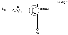
Several digits were faint and incomplete on an SR-10. Close examination revealed the culprit to be an SN27423 chip, apparently a hex driver buffer. Indeed, when I swapped the two SN27423 in the machine, the bad digits and good digits were swapped on the display. I have no replacement SN27423, but I had enough information to deduce its pinout: 2->3, 5->4, 7->6, 10->11, 12->13, 15->14; pins 8 and 9 are on VDD (we don't care about pins 1 and 16.) I was able to replace the six buffers in this chip with a simple circuit, shown here:
Compared to the circuit solutions recommended by Texas Instruments (essentially, a Darlington circuit of two transistors and several resistors) this solution is a bit simplistic, but it works; and best of all, there is enough room inside the calculator for the six extra transistors and six resistors needed.
In this TI-66, memory contents were randomly altered. Every attempt to read from memory yielded a different result, at all program/registry locations. Examination of the circuit revealed that the memory is an obsolete off-the-shelf chip: a Toshiba 5514 C-MOS chip with 1kx4 bits of capacity. I was able to acquire replacement chips from a UK supplier and repair this calculator; it now works like new.
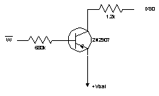
In this TI-66, memory always read a '1' in the 1 bit, causing numbers and program instructions to be corrupted. For instance, after clearing a register, its contents read 1.1111111E11. Having recently acquired replacement memory chips, I decided to try a replacement here, but to no avail; the problem remained. The conclusion was that the failure is on the main logic chip, i.e., the calculator is not repairable. However, I didn't give up; I decided to give it another try. Disconnecting the processor from the affected bit in memory, I was able to confirm that the processor is able to read data just fine; the problem was with writing data. I was also able to confirm that what the processor reads as a '1' actually appears as a logic 'low' in RAM and vice versa. I now had a simple plan: why don't I try and 'help' the processor with a pull-up resistor? Assuming its output circuit is damaged, but still provides a weakened signal, maybe a resistor with the right value will be sufficient to reliably fix the problem? Guess what... it worked. Experimentation showed that connecting the affected bit to power via a 1.2k resistor fixed the problem, and the machine began to operate normally. Not for too long, unfortunately; after a few minutes, I noticed that bit errors began to appear. I also noticed signs that the batteries might be weakening! A quick measurement confirmed that there was excessive current draw via my newly installed resistor, and the solution was also sensitive to battery voltage. So I tried another solution. After all, I only need the pull-up resistor when the processor is actually writing to memory; and I know very well when that is, because there's a separate write signal that I can tap. So instead of connecting the resistor directly, I decided to insert a transistor controlled by the write signal to switch on the resistor when needed:
This solution solved the problem with excessive current nicely. The calculator remains sensitive to decreasing battery voltage, but it appears to operate well for a reasonable range of normal battery voltages.
This was a most curious case: I had not one, but two HP-67 calculators that were able to write magnetic cards just fine, but always displayed Error when I tried to read a card. Curiously, the two calculators weren't even of the same vintage: notable differences were present internally.
It was easy to trace the problem to the calculators' processor boards: when swapped, the processor boards continued to malfunction even with "known good" card readers. Therefore, I have eliminated the obvious: the problem was not with the motor, the read-write head, or the sense amplifier circuit. The next obvious choice was the Card Reader Chip, the CRC, on the processor board; however, even after swapping with a "known good" CRC, the problem remained.
During my tests, I noticed that the problem disappeared when the battery was run down and the low power LED was lit. I did some tests using various test voltages (connecting a silicone diode in series with 3 good "AA" alkaline batteries is an easy way to get the desired voltage) and I was able to confirm that at the reduced voltage, the calculator operated reliably. The obvious culprit therefore was the calculator's internal DC-DC power supply; with an oscilloscope, I indeed found excessive noise on the -12VDC supply line on one of the CPU boards. Replacing a tantalum capacitor was sufficient to remedy that problem, but the calculator continued to malfunction.
I was about ready to start desoldering all the chips on this CPU board when I was advised to try and replace another capacitor, this one between vbatt and ground. I didn't believe that this capacitor was bad (a check with my oscilloscope showed no appreciable noise on vbatt), but I decided to replace it anyway. To my surprise, the board began to function correctly immediately afterwards. The conclusion is that this capacitor, while it still measured the correct capacitance, may have developed an excessive Equivalent Series Resistance, or ESR, and was no longer able to filter the spike on vbatt at motor startup. The fix solved the problem on both faulty CPU boards.
Usually, if the same segment is dead across all digits in a calculator, the segment driver is suspect. In the case of the HP-67, the segment driver chip is the smaller of two chips located underneath the LED display modules. It is easy to map this chip's inputs and corresponding outputs. This chip contains seven independent driver circuits. When a single segment is dark across the entire display, chances are that one of the driver circuits is dead. Replacing the entire chip is often not an option, since substitute chips are hard to find. However, a single driver element can be replaced using a 2N4401 transistor. The base of the transistor should be connected to the corresponding input, the emitter to the corresponding output, and the collector to pin 15 of the segment driver chip. Using fine wire-wrap wire, you can place the transistor in such a way so that the keyboard/display PCB still fits snugly against the calculator's plastic backbone, and the case can be closed securely. If the driver circuit in the segment driver chip is shorted, it may be necessary to disconnect (cut) one or both corresponding pins in order for the substitute transistor to work correctly.


